Assignment 2 - initial CAD design
Planning
For this assignment we were asked to design our project idea in Cad. The first step to accomplish this, was to figure out the general dimensions of the project. In my case the dimensions were heavily restricted by the parts I wanted to use. To account for all this I decided to model the most important parts in CAD aswell so that I would be able to design around them. The parts I decided to model were the following:
- Arduino Uno
- 18650 Li-Ion battery
- Cherry MX key switch
These componets were chosen because they are the most important parts of the project. The Arduino is the brain of the project, the battery is the power source, the key switch is the input and the power switch is the on/off switch.
Designing the Key switches
Step 1 - Key switch upper half
To design the Cherry key switch I referenced the design files that Cherry helpfully provides on their developer Website. After importing the image into Fusion360 I started by sketching and extruding the upper half of the switch. The important element for this aspect was, to include the angle during the extrude procedure to create the dome shape. The lower half followed by doing the same thing, but with a different angle and in the opposite direction.
Step 2 - Stem inset
The next important feature for a mechanical keyswitch is the stem. This is the part of the switch which will later interact with the keycap, and by extension the user. To achieve this a small sqaure was inset into the upper half of the key switch. After doing this an even smaller square could be extruded to create the stem. The last step for the stem was to include the cross shape on the top of the stem. This was done by sketching a cross shape on the top of the stem and then extruding it.
To finish the design I also modeled the bottom stump and the two pins on the underside of the switch. The following is the result of this process:
Final result - Top-down angle view
Final result - side view with pins
Designing the Arduino
Step 1 - Arduino outline
The modeling process for the arduino followed a similar path. In this case I used the official Arduino Uno R3 documentation as a reference. The first step was to sketch the outline of the board. This was done by creating a sketch on the top plane and then tracing the outline of the board. After this the outline was extruded to the correct height. After doing this the next step was to add the I/O-Ports of the arduino. I included the GPIO-Pins present on the board itself, the DC-5V barrel jack, and the USB port on the side of the board. Modeling these additional ports followed the same principles as before of sketching, extruding and insetting if necessary.
 (Final result Arduino)
Designing the Battery
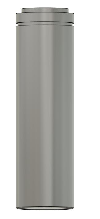
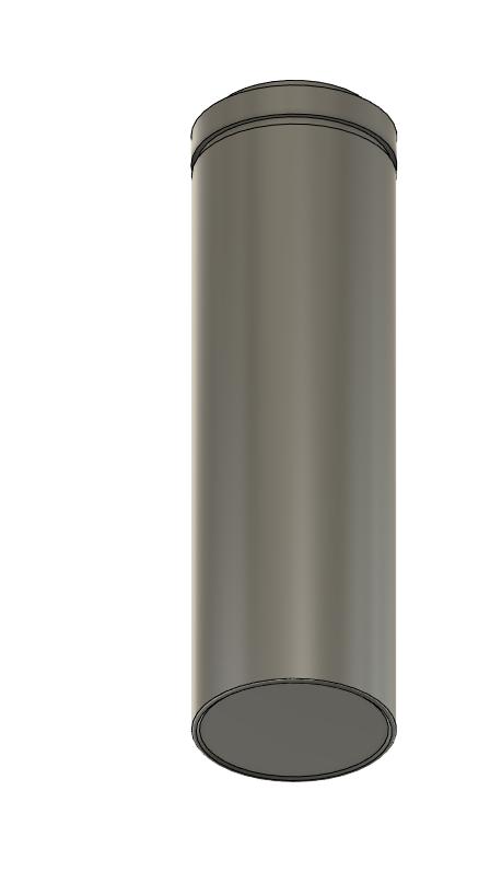
Designing the battery was the easiest part of this assignment, as it just consists of a cylinder. The only thing that had to be taken into account was the dimensions of the battery. To achieve this I used one of the many datasheets for a 18650 battery cell. The only thing that had to be done was to create a cylinder with the correct diameter and height. The following is the result of this process:
Designing the Case
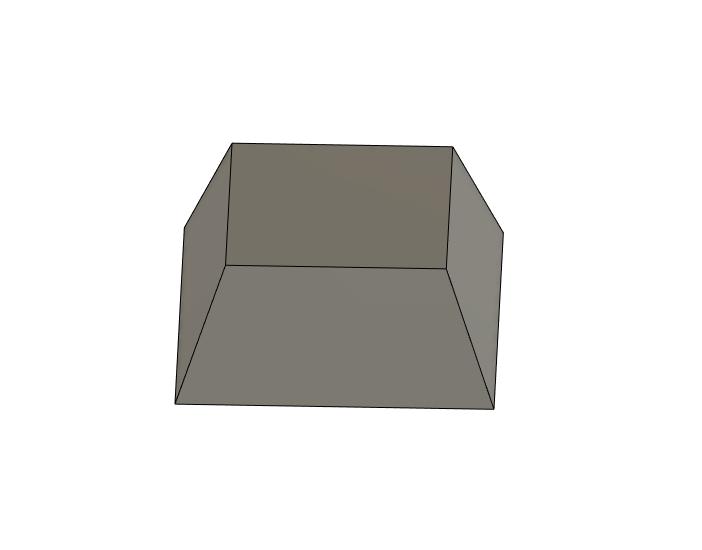
Step 1 - Basic planning
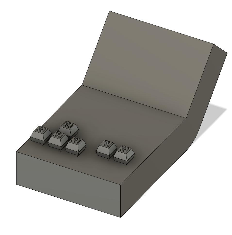
The first step to design the case was to figure out the rought dimensions. To due this I copied the amount of key switches I wanted to include in the design and started to arrange them. After figuring out the layout I wanted to go with, I started sketching out the rought shape around them. I did this by creating the side profile of the device to easily be able to include a curved angle. After extruding this sketch I was left with a mesh that resambled the design I was going for.
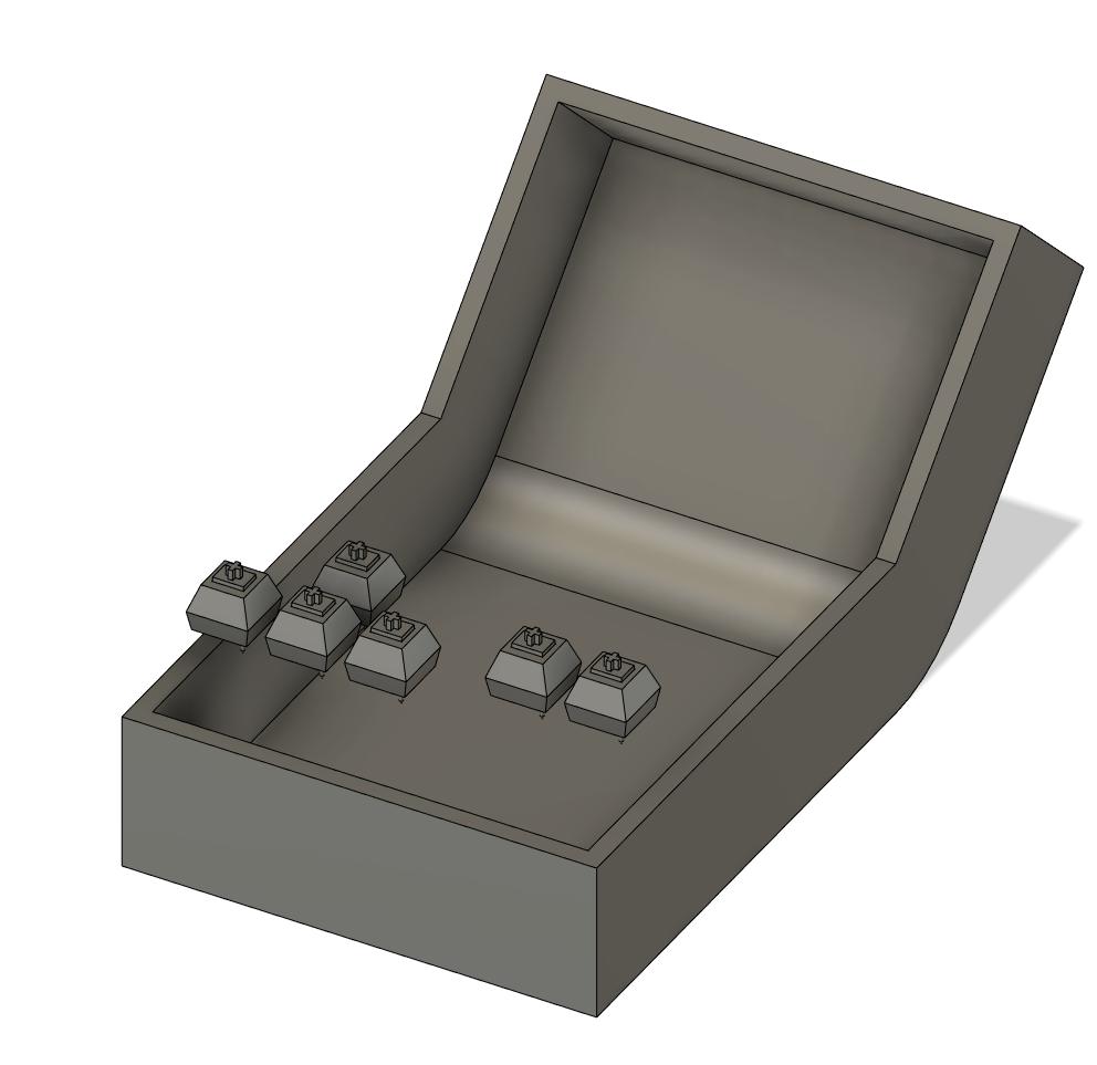
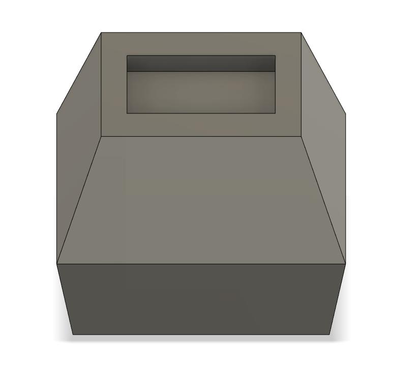
Step 2 - Hollow shell
To be able to include the parts I already designed I used the shell operation to create a hollow shell. This left me with a hollow shell that was open on the top. This open area could then be filled with my previously created components. This shell would also be what I could eventually 3D-Print.
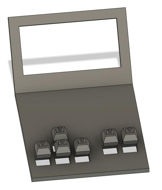
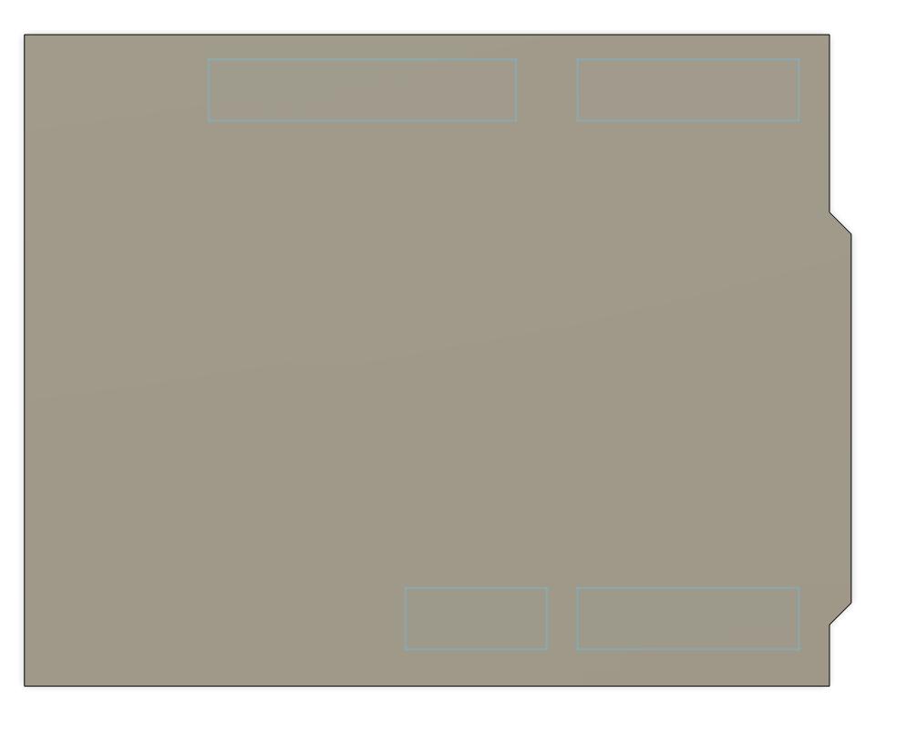
Step 3 - Top plate
To be able to use the device I would however need a way to close the shell. To achieve this I traced the upper edge of the shell I created a thin cover piece. Into this piece I then cut out the holes for the key switches and the screen. This cover piece could then be used to close the shell. To fix this cover to the rest of the shell I intend to either use screws or glue. The main reason to decide against screws would be the fact that I currently use a rather thin shell that would not be able to hold screws.
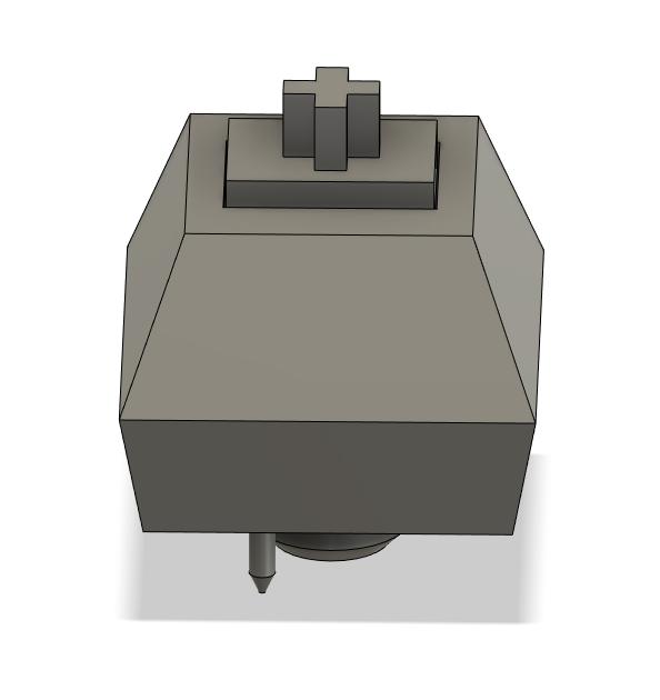
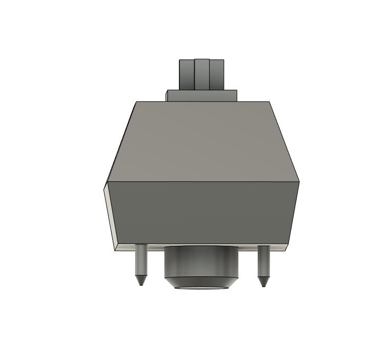
Step 4 - Toggle switch
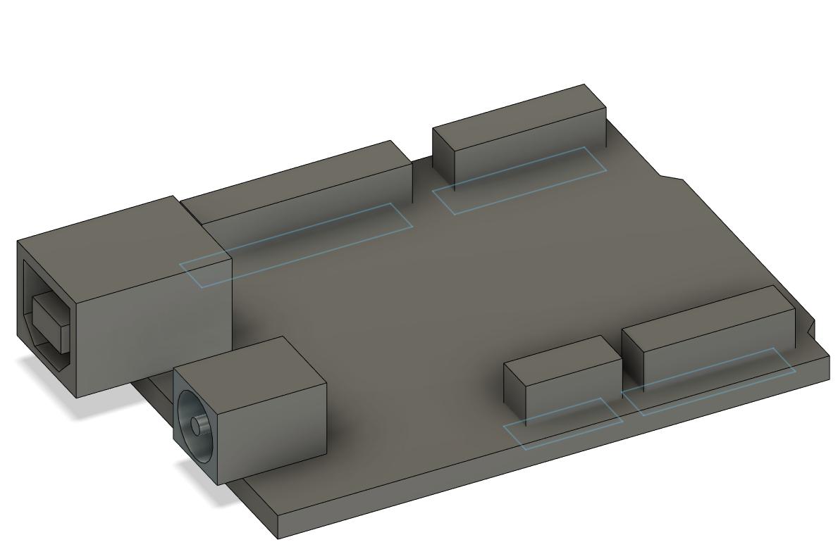
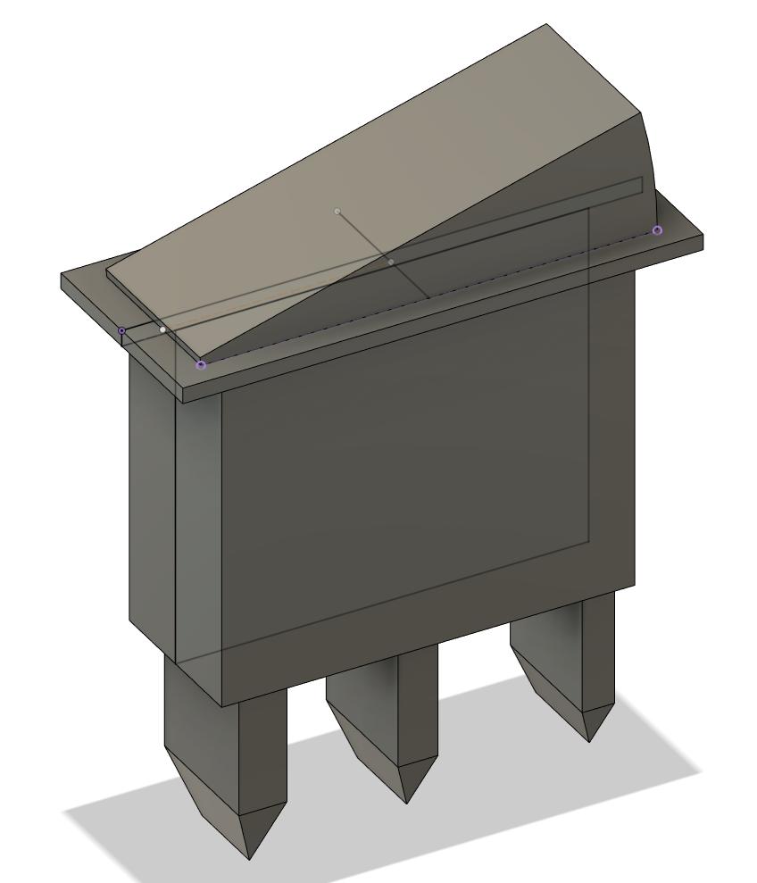
I could now plan the internals of the case. For this I loaded the previously created models into the same workspace as the shell I created. I then started to arrange the parts in the shell. While doing this, I realised I would also need a way to toggle the power of the device. To achieve this I decided to include a small switch on the side of the device. This switch would then be wired in series to battries and the rest of the intenrals. I did this by modelling this Rocker switch.
I could now place all of the components into the shell. To correctly create the holes for the toggle switch and the ports of the arduino I used the Boolean operation. This operation allowed me to cut out a shape from another shape. After cutting out the neccessary holes in the shell I was left with the following result:
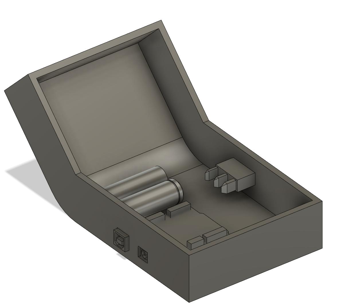 (Final result Mechboy bottom shell)
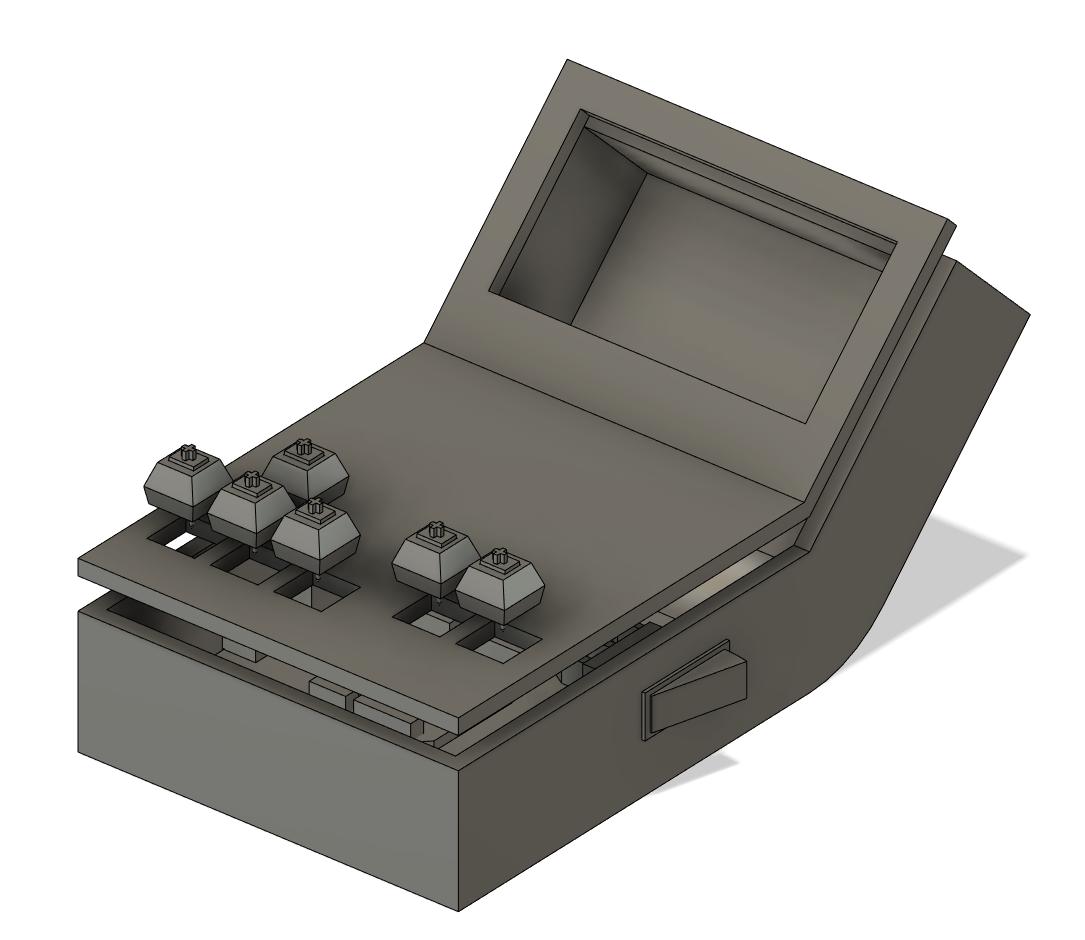 (Final result Mechboy top plate)
Files:
All model files and reference images used can be found here