Assignment 6 - Embedded Programming
Assigment
This weeks assignment was to create a circuit board using an Arduino to control multiple LEDs. We were tasked to control 3 LEDs using 2 push buttons as controls elements.
To achieve this, my plan was to have one of the buttons act as a “plus-switch” and the other one as a “minus-switch”. The plus switch would increase the number of LEDs that are turned on, while the minus switch would decrease the number of LEDs that are turned on. The LEDs would be turned on in a sequence, starting with the first LED and ending with the third LED.
Board simulation
The first step to creating the board was to create a schematic for the board. This schematic was created using Tinkercad. This would allow me to easily test different board layouts and see if the board would work as intended.
The first step to create this board was to create a basic schematic using multiple LEDs.
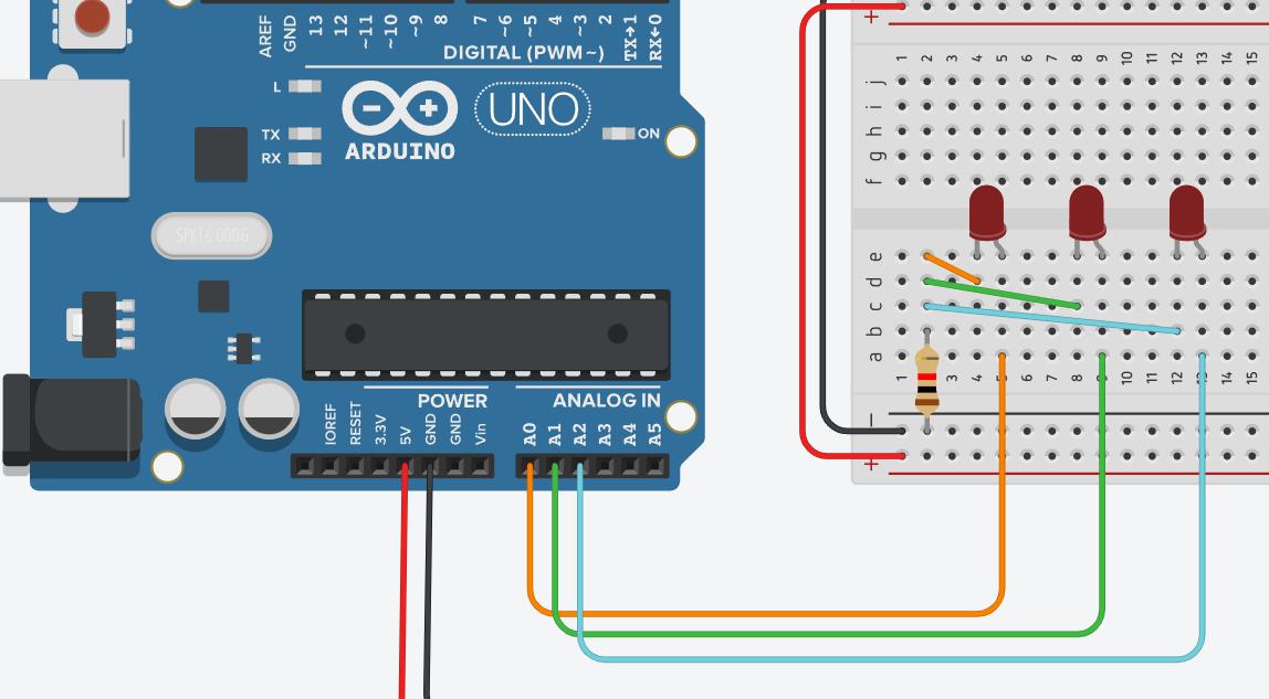
In this example the LEDs are connected to the pins A0, A1 and A2. The LEDs are all connected via a shared resistor to a common ground. Through this the LEDs can be turned on and off by setting the pins to HIGH or LOW.
void setup()
{
    pinMode(A0, OUTPUT);
    pinMode(A1, OUTPUT);
    pinMode(A2, OUTPUT);
}

void loop()
{
    digitalWrite(A0, HIGH);
    delay(1000);
    digitalWrite(A0, LOW);
    digitalWrite(A1, HIGH);
    delay(1000);
    digitalWrite(A1, LOW);
    digitalWrite(A2, HIGH);
    delay(1000);
    digitalWrite(A2, LOW);
}
This sketch would have all of the LEDs blinking one after another.
The next step was to include the switches. The setup with the switches was wired up as follows:
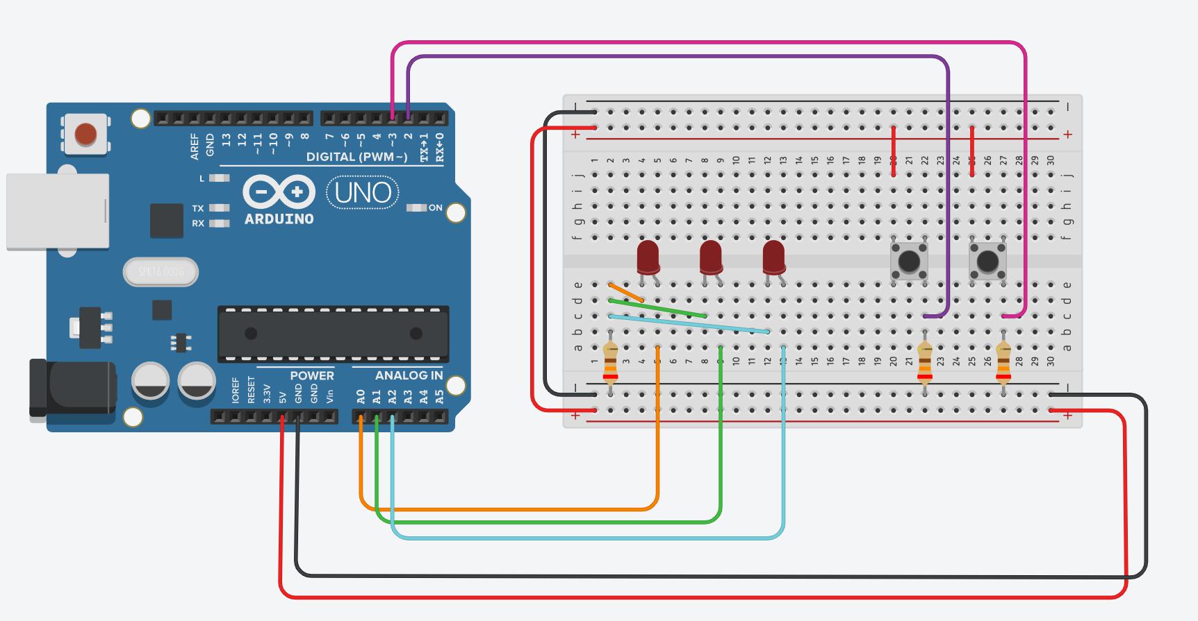
The switches were connected to the digital pins 2 and 3. The switches were also connected to the 5V pin and the ground pin.
One of the buttons could now be used as following to toggle whether the LEDs would be set to HIGH or LOW
void setup()
{
    pinMode(A0, OUTPUT);
    pinMode(A1, OUTPUT);
    pinMode(A2, OUTPUT);
    pinMode(2, INPUT);
}

void loop()
{
    if (digitalRead(2) == HIGH)
    {
        digitalWrite(A0, HIGH);
        digitalWrite(A1, HIGH);
        digitalWrite(A2, HIGH);
    }
    else
    {
        digitalWrite(A0, LOW);
        digitalWrite(A1, LOW);
        digitalWrite(A2, LOW);
    }
}
To now be able to also toggle the LEDs on and off, the second button was added. This button was connected to the digital pin 3. The button was also connected to the 5V pin and the ground pin.
Both buttons could now be used with the following code, to toggle the amount of LEDs connected:
int ledCount = 0;

void setup()
{
    pinMode(A0, OUTPUT);
    pinMode(A1, OUTPUT);
    pinMode(A2, OUTPUT);
    pinMode(2, INPUT);
    pinMode(3, INPUT);
}

void loop()
{
    if (digitalRead(2) == HIGH)
    {
        ledCount++;
        if (ledCount > 3)
        {
            ledCount = 0;
        }
    }
    if (digitalRead(3) == HIGH)
    {
        ledCount--;
        if (ledCount < 0)
        {
            ledCount = 3;
        }
    }
    if (ledCount == 0)
    {
        digitalWrite(A0, LOW);
        digitalWrite(A1, LOW);
        digitalWrite(A2, LOW);
    }
    else if (ledCount == 1)
    {
        digitalWrite(A0, HIGH);
        digitalWrite(A1, LOW);
        digitalWrite(A2, LOW);
    }
    else if (ledCount == 2)
    {
        digitalWrite(A0, HIGH);
        digitalWrite(A1, HIGH);
        digitalWrite(A2, LOW);
    }
    else if (ledCount == 3)
    {
        digitalWrite(A0, HIGH);
        digitalWrite(A1, HIGH);
        digitalWrite(A2, HIGH);
    }
}
This code works in theory, however it has the major flaw that the buttons are not debounced. This means that the buttons will not work as intended, as pressing the buttons for even just a split-second will register as multiple button presses. To fix this issue, the buttons need to be debounced. This can be achieved using additional variables to track the previous state of the buttons. The code for this looks as follows:
bool buttonMinusLastState = false;
bool buttonPlusLastState = false;
int ledCount = 0;

void setup()
{
  pinMode(A0, OUTPUT);
  pinMode(A1, OUTPUT);
  pinMode(A2, OUTPUT);
  pinMode(2, INPUT);
  pinMode(3, INPUT);
}

void loop()
{
  bool buttonMinusState = digitalRead(2);
  bool buttonPlusState = digitalRead(3);

  if(buttonMinusState != buttonMinusLastState)
  {
    if(buttonMinusState)
    {
      if(ledCount > 0)
      {
        ledCount--;
      }
      buttonMinusLastState = true;
    } else {
      buttonMinusLastState = false;
    }
  }

  if(buttonPlusState != buttonPlusLastState)
  {
    if(buttonPlusState)
    {
      if(ledCount < 3)
      {
        ledCount++;
      }
      buttonPlusLastState = true;
    } else {
      buttonPlusLastState = false;
    }

  }

  if(ledCount > 0){
    digitalWrite(A0, HIGH);
  } else {
    digitalWrite(A0, LOW);
  }

  if(ledCount > 1){
    digitalWrite(A1, HIGH);
  } else {
    digitalWrite(A1, LOW);
  }

  if(ledCount > 2){
    digitalWrite(A2, HIGH);
  } else {
    digitalWrite(A2, LOW);
  }

}
This code now works as intended. The LEDs can now be toggled on and off using the buttons. The LEDs will also be toggled in a sequence, starting with the first LED and ending with the third LED.
Using this code, the final simulation result would behave like this:
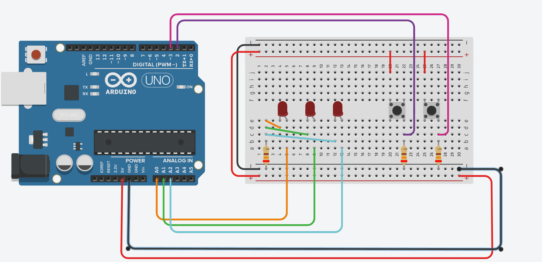
The .brd-File for this schematic can be found here
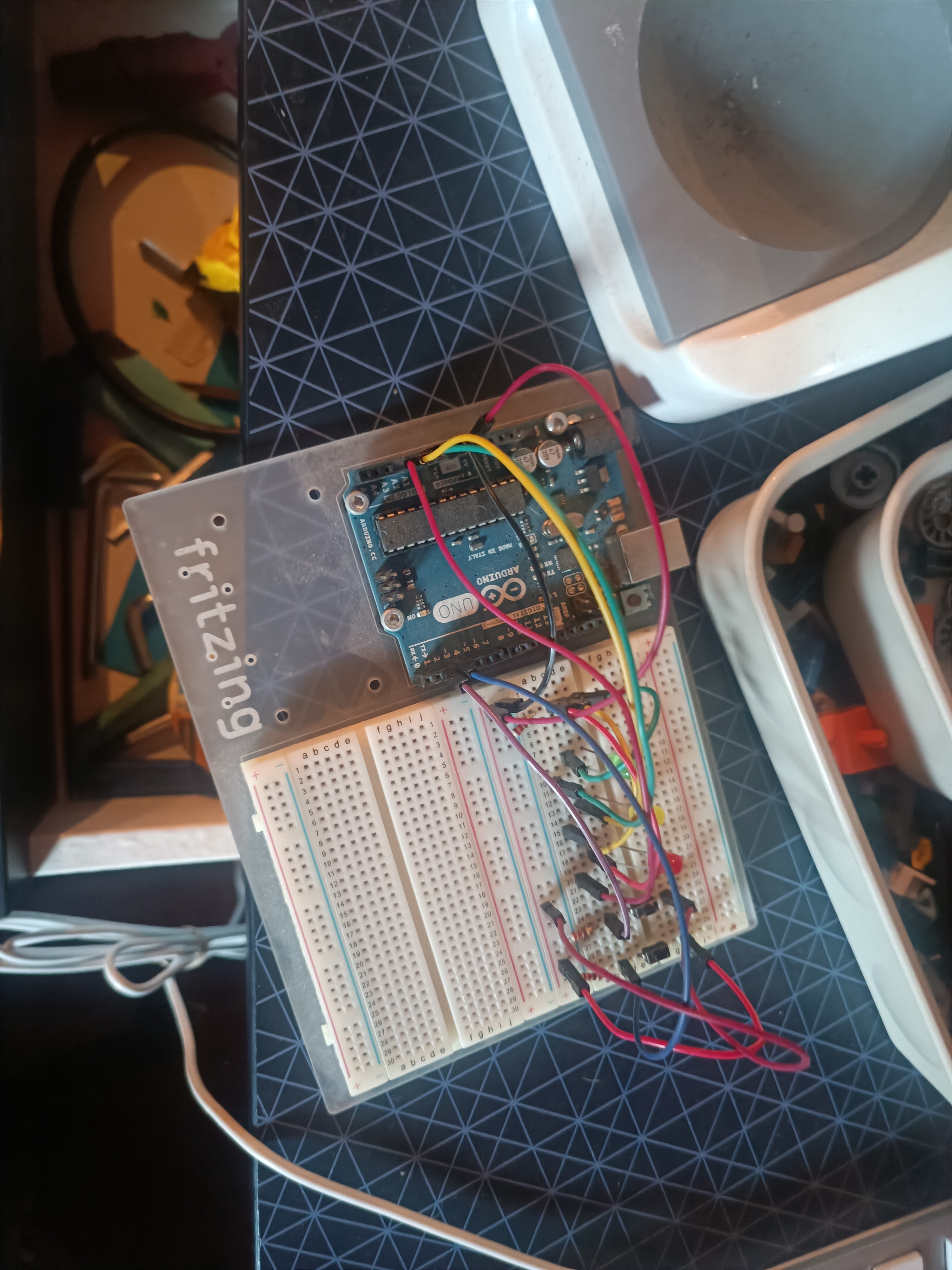
Board creation
Creating the board was pretty easy after the Simulation. The parts needed for this circuit were as followed:
- Arduino Uno
- 3 LEDs
- 2 Push Buttons
- 3 ~220Ω Resistors
- lots of jumper wires
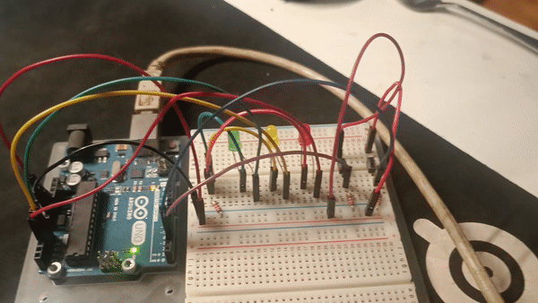
With these Components it was easy to recreate the Schamtic on a breadboard. The final result looked like this:
After flashing the code previously written in TinkerCAD onto the Arduino, the board worked as intended. The LEDs could be toggled on and off using the buttons. The LEDs would also be toggled in a sequence, starting with the first LED and ending with the third LED.