Assignment 7 - Input / Output Devices
Assignment
This weeks assignment was to create circuit using a combination of input and output devices. The circuit should include at least two input device and two output device. The input device should be used to control the output device.
Simulation
Before assembling all of this in the real world, I first created a simulation of the circuit using Tinkercad. This would allow me to easily test different board layouts and see if the board would work as intended.
Potentiometer
My first input device is a potentiometer. The potentiometer is connected to the Arduino as follows:
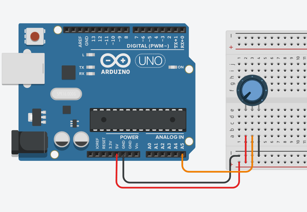
It acts as a voltage divider. The voltage on the middle pin is dependent on the position of the potentiometer. The voltage can be read by using the analogRead-Function. The following code was used to read the potentiometer:
const int potPin = A5;
void setup()
{
  pinMode(potPin, INPUT);
  Serial.begin(9600);
}

void loop()
{
  int val = analogRead(potPin);
  Serial.println(val);
}
In this simple example the value read from the potentiometer is printed to the serial monitor.
Ultrasonic Sensor
My second input device is an ultrasonic sensor. The ultrasonic sensor is connected to the Arduino as follows:
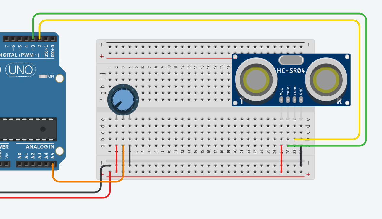
The ultrasonic sensor has two data pins, one for the trigger and one for the echo. The trigger pin is connected to pin 3 and the echo pin is connected to pin 2. The ultrasonic sensor is controlled by sending a 10µs pulse to the trigger pin. The sensor then sends out an ultrasonic pulse and waits for it to return. The time it takes for the pulse to return is then used to calculate the distance. The following code was used to read the ultrasonic sensor:
float duration, distance;
const int trigPin = 3;
const int echoPin = 2;

void setup()
{
  pinMode(trigPin, OUTPUT);
  pinMode(echoPin, INPUT);
  Serial.begin(9600);
}

void loop() {
  digitalWrite(trigPin, LOW);
  delayMicroseconds(2);
  digitalWrite(trigPin, HIGH);
  delayMicroseconds(10);
  digitalWrite(trigPin, LOW);
  duration = pulseIn(echoPin, HIGH);
  distance = (duration*.0343)/2;
  Serial.print("Distance: ");
  Serial.println(distance);
  delay(100);
}
In this example the distance is printed to the serial monitor every 100ms.
Buzzer
My first output device is a buzzer. The buzzer is connected to the Arduino as follows:
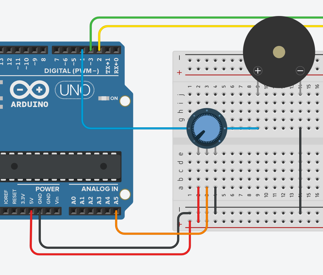
It sits directly inline between the ground pin and pin 4. The buzzer is controlled by setting pin 4 to HIGH or LOW. The following code was used to control the buzzer:
const int buzzerPin = 4;

void setup()
{
  pinMode(buzzerPin, OUTPUT);
}

void loop() {
  digitalWrite(buzzerPin, HIGH);
  delay(100);
  digitalWrite(buzzerPin, LOW);
  delay(100);
}
In this exmaple the buzzer is turned on and off every 100ms.
I2C Display
My Second output device is an I2C Display. I used the LiquidCrystal_I2C-Library to control it. The Library can be installed via the Arduino IDE Library Manager. The I2C Display is connected to the Arduino as follows:
To control the output on the display, the following code was used:
#include <LiquidCrystal_I2C.h>


LiquidCrystal_I2C lcd(0x20,16,2);

void setup() {
  lcd.init();
  lcd.backlight();
  lcd.print("Test");
  lcd.setCursor(0,1);
  lcd.print("Test2");
  delay(10);
}

void loop() {
  lcd.setCursor(0,1);
  lcd.print("Test3");
  delay(10);
}
The important part is the LiquidCrystal_I2C lcd(0x20,16,2);. The first parameter is the address of the display. The second parameter is the number of columns and the third parameter is the number of rows.
The Adress of the display can vary, this proved to be a problem later when implementing the final circuit in the real world. For the simulation, the address was set to 0x20. The address can be found out by using the I2C Scanner-Sketch from the Arduino IDE Examples.
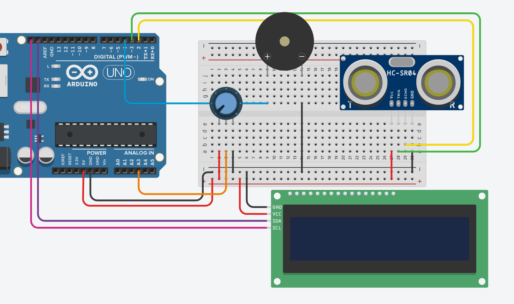
Combination
The combined Circuit can be viewed on Tinkercad.
The purpose of this Circuit is to display the current value of a potentiometer on an LCD Display. If the distance measured by the Ultrasonic Sensor is below 100mm, the Buzzer will be activated. To achieve both of these Tasks the code from the previous examples was combined.
I first read both, the potentiometer and the ultrasonic sensor. I then mapped the potentiometer value to a percentage value. This percentage value was then displayed on the LCD Display. If the distance measured by the ultrasonic sensor was below 100mm, the buzzer would be activated.
Real-World Implementation
The assembled circuit looks as follows:
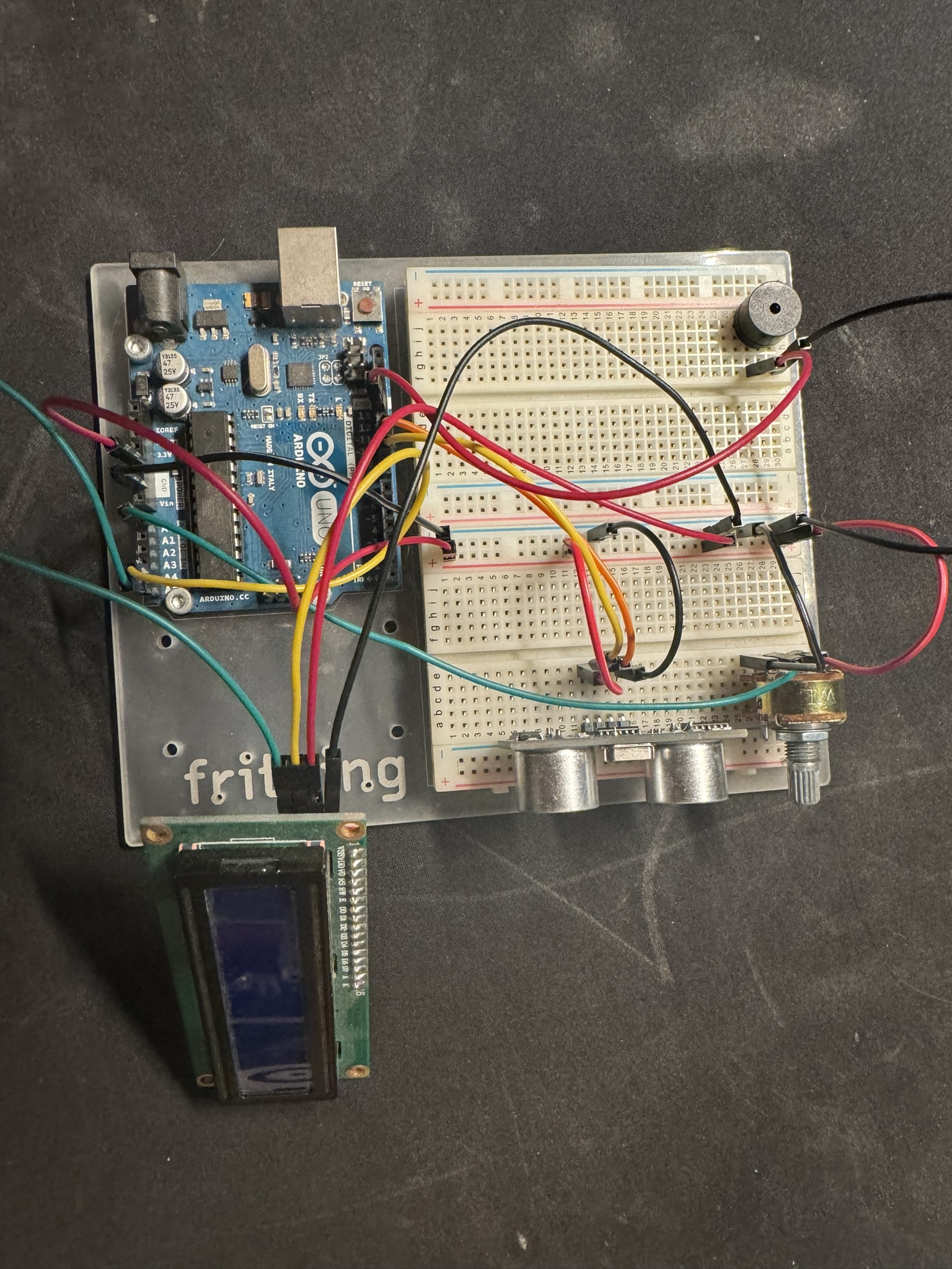
This circuit follows the previously designed layout pretty closely. On of the main differnces is the pins to which the individual devices were connected.
The Code used is also very similar to the previously tested Code. The only difference is the address of the LCD Display. The address of the LCD Display used in the real world is 0x27. This address was found out by using the I2C Scanner-Sketch from the Arduino IDE Examples.
Modified Code:
#include <LiquidCrystal_I2C.h>

LiquidCrystal_I2C lcd(0x27, 16, 2);
const int potPin = A0;
const int trigPin = 9;
const int echoPin = 10;
const int buzzerPin = 13;

void setup() {
  Serial.begin(9600);

  // Ultrasonic
  pinMode(trigPin, OUTPUT);
  pinMode(echoPin, INPUT);


  // LCD
  lcd.init();
  lcd.backlight();
  lcd.setBacklight(50);
  lcd.print("Potentiometer:");
  lcd.setCursor(0, 1);
  lcd.print("0% Turned");

  // Potentiometer
  pinMode(potPin, INPUT);

  // Buzzer
  pinMode(buzzerPin, OUTPUT);
}

void loop() {
  // Read Values

  // Distance
  digitalWrite(trigPin, LOW);
  delayMicroseconds(2);
  digitalWrite(trigPin, HIGH);
  delayMicroseconds(10);
  digitalWrite(trigPin, LOW);
  float duration = pulseIn(echoPin, HIGH);
  float distance = (duration * .0343) / 2;
  Serial.println("Distance: " + String(distance));

  // Potentiometer
  int potValue = analogRead(potPin);
  Serial.println("PotValue: " + String(potValue));

  // Play Sound if distance is below 100mm
  if (distance <= 100) {
    digitalWrite(buzzerPin, HIGH);
    delay(10);
  }
  digitalWrite(buzzerPin, LOW);

  // Update Display
  int percent = map(potValue, 0, 1023, 0, 100);
  lcd.setCursor(0, 1);
  lcd.print(String(percent) + "% Turned");
  delay(100);
}
A demo of the Circuit working as described can be viewed here