Assignment 9 - Electronics Design
Assignment
This weeks assignment was to design a PCB for the final project using KiCad. The board should be designed to be produced using the CNC machines in the FabLab as done in the previous assignment. The board should be designed to be use the ATTiny 1614 microcontroller if possible.
Microcontroller
The board could then be programmed using the updi programmer produced in the previous assignment. The ATTiny 1614 is a 14 pin microcontroller with 12 GPIO pins. Of these pins, 2 pins were capable of beeing used for a uart serial connection. 2 more pins were capable of the hardware integrated I2C interface. This would leave a project using both, the Serial and I2C interface with anoter 8 GPIO pins.
As I already had a basic Idea for what my project was going to need later I was able to decide that the ATTiny 1614 would have enough I/O capability for my project.
Schematic
The first step in this process was to design the schematic for the board. The schematic was designed using KiCad. We used the FabAcademy KiCad Component Library for the footprint and general schematics used in this process.
The purpose of the schematic was to decide which components would end up connected to each other.
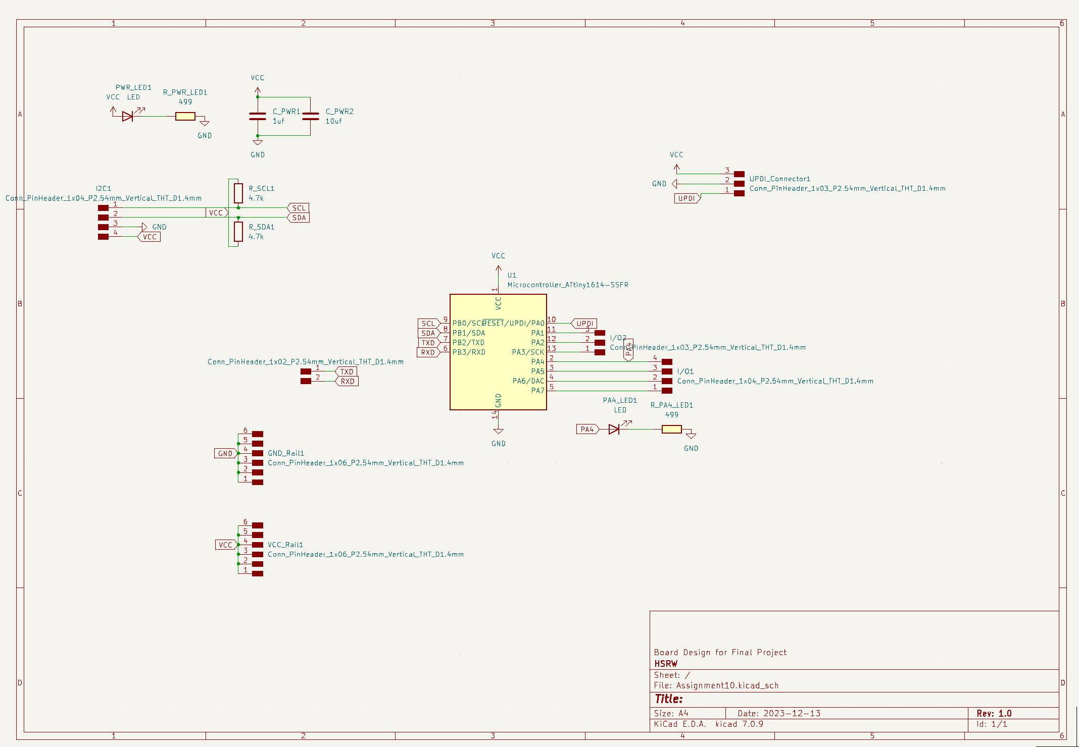
The schematic was designed to include the ATTiny 1614 microcontroller, a power LED, capacitors for the power supply and pinheaders for all interfaces to the microcontroller. This included the UPDI interface, the I2C interface and the Serial interface.
The I2C interface also got its pair of complementary 4,7k resistors. The board also got 6 pins each for VCC and Ground as this could later be used to easily provide power for all other components used in the project.
The final schematic ended up looking like this:
Design
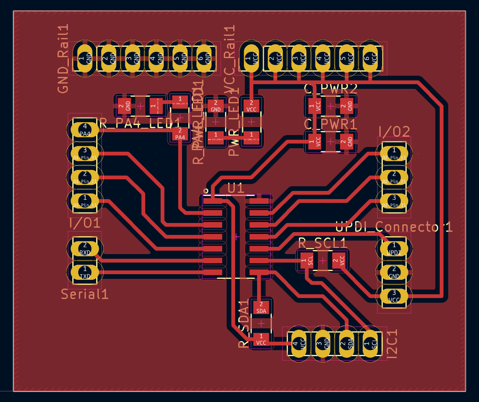
The next step was to design the layout of the circuit board. The layout was designed using the circuit board designer in KiCad. The layout was designed to be produced using the CNC machine in the FabLab. The board was designed to be produced using “isolation routing”. As base stock we used FR-4 copper clad board. As the board would be produced using the hand soldering, the components were placed in a way that would make it easy to solder them to the board. As the board mostly acted as a breakout board for the microcontroller, the routing of the traces was relatively simple.
The final layout ended up looking like this:
Production
The next step was to produce the board using the CNC machine. The production process was the same as in the previous assignment. The machine was setup to use a universal 0.2mm cutter and the isolation routing process was used to produce the board.
The soldering of the components was also the same as in the previous assignment. The components used mostly consisted of SMD components and pinheaders. The resistors, capacitors and LED’s used were all in the 1206 package format. The most important component was the ATTiny 1614 chip in the center of the board.
Testing
After production the board was also tested using a multimeter to check for shorts and continuity. The board was then connected to a computer using the UPDI programmer from last weeks assignment. Using this I was able to successfully program the ATTiny 1614 microcontroller using the Arduino IDE.
Files
All of the KiCad files used in this process can be found here.