Fundementals of digital fabrication - Final Project
Idea
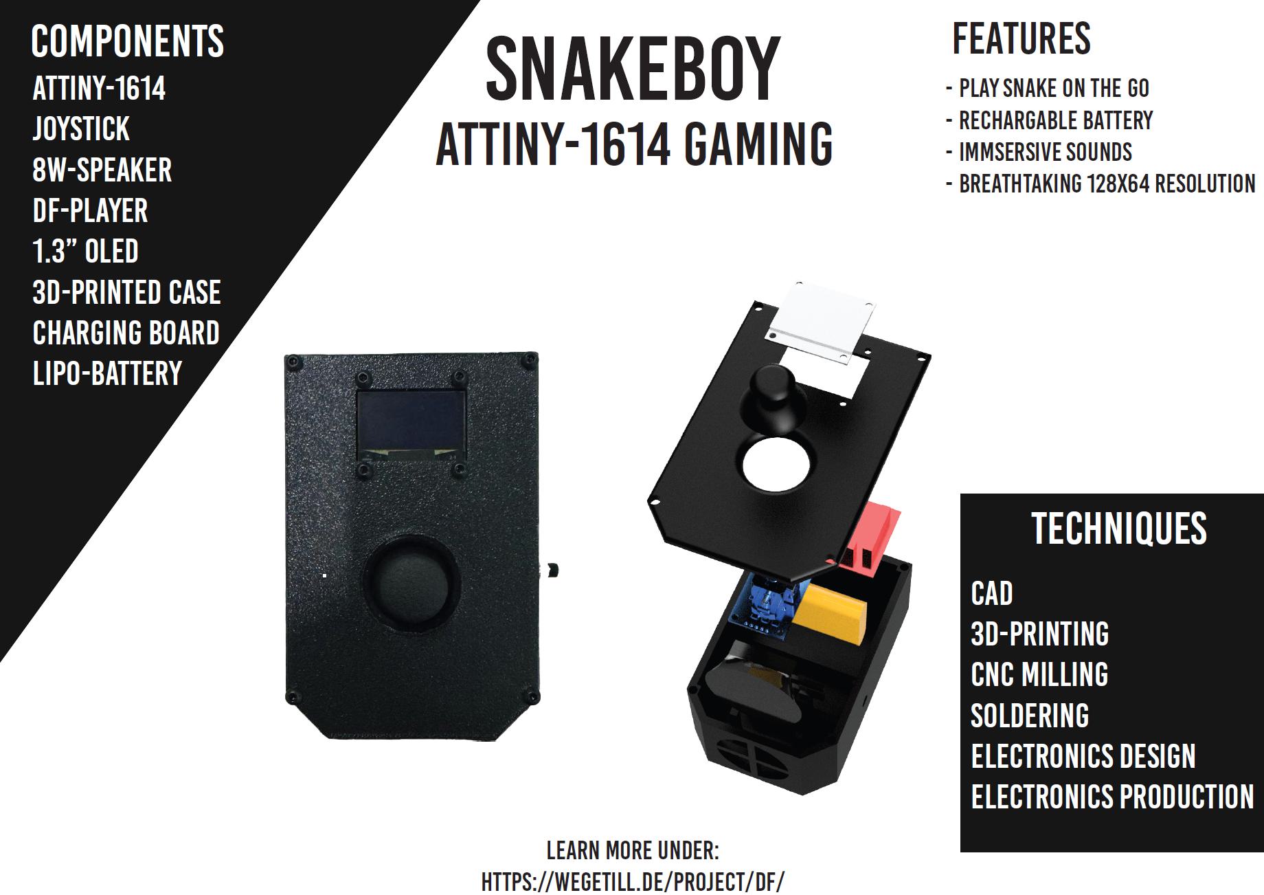
The goal for this course was learn the basics of digital fabrication. This was achieved by completing a series of assignments in which we were tasked with using the different methods. For our final project we were given the opportunity to use the skills we learned to create a project of our own choosing. I decided to create a game console that would be able to play the classic game “Snake”. The console would be based on an ATtiny microcontroller and would be made using the skills I learned during the course.
I choose to create a game console because I wanted to create something that would be fun to use and easy to understand. The game “Snake” was chosen because it is a simple game that is easy to implement and a well-known classic.
Throughout the course this idea went through multiple different iterations. The initial version of this idea can be found here.
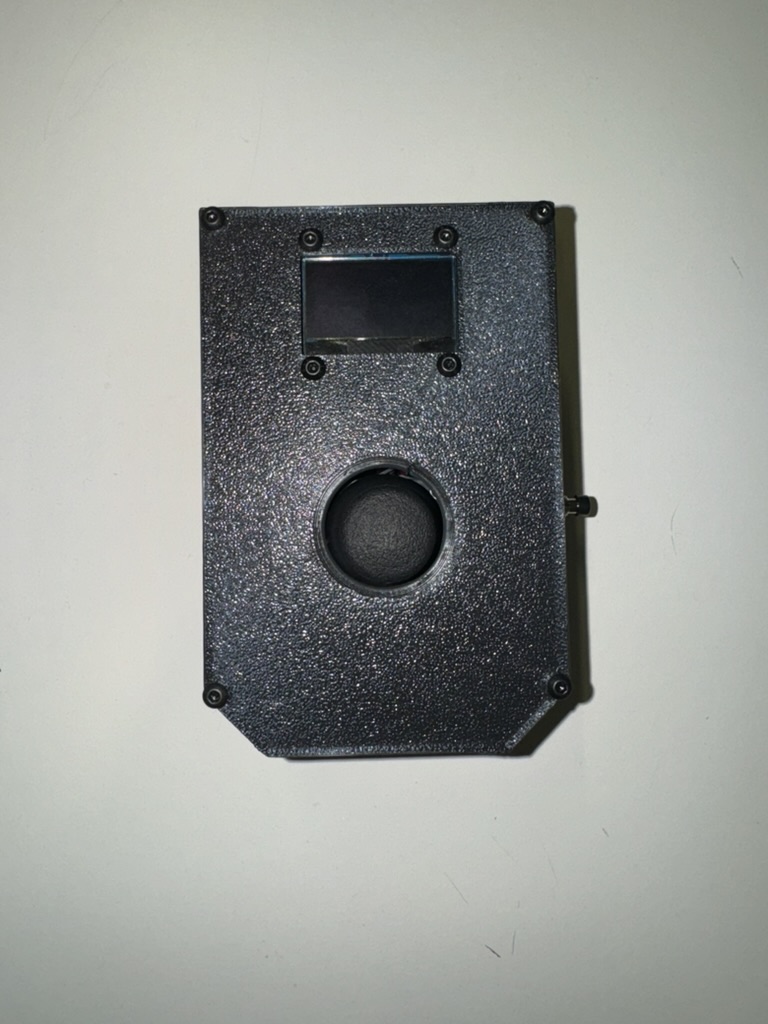
Case Design
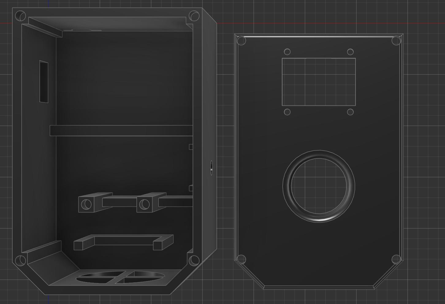
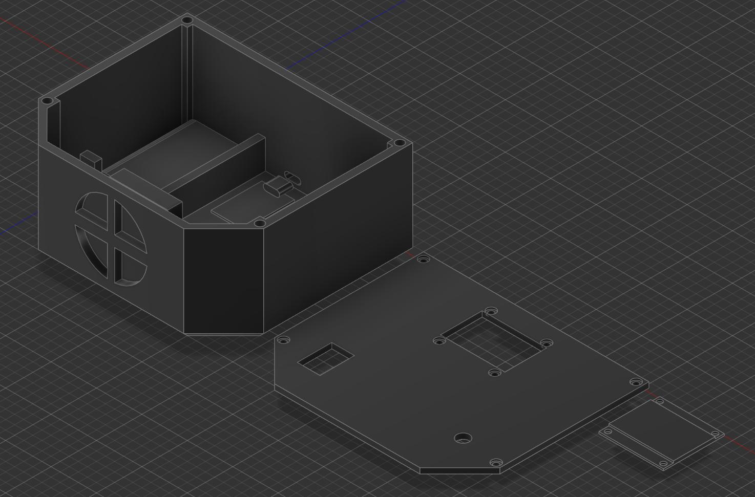
My idea was to fabricate the case using 3D-Printing. I chose this method primarily as I was already familiar with 3D-Printing and the necessary considerations I would have to make for the design. The case was designed using Fusion 360. The case was designed to be as small as possible while still being able to house the necessary components. The case was designed to be printed in two parts, the.
The top part of the case would house the screen and have a cutout for the joystick. The bottom part of the case would house the microcontroller and all other components. The case was designed to be held together using screws. As screwing into plastic (and especially 3D-Printed parts) can be difficult, I chose to use heat-set inserts to make the case easier to assemble. These inserts could be heated up using a soldering iron and then pressed into the plastic. Once cooled down, the inserts would be held in place by the plastic and would allow for screws to be used to hold the case together.
The case would also need to provide the specific cutouts and mounting points for the different components. This included a cutout for the USB-C charging board, a cutout for the reset button, a hole at the bottom of case for the speaker, mounts in the lower half and a cutout at the top-plate for the joystick, and a cutout with mounting hole in the top-plate for the screen.
Internally the case also got divided into multiple smaller compartments. The battery would be housed in a separate compartment at the bottom of the case between the speaker and the controller compartment. The speaker in the bottom got a mounting bracket such that it would be held in place by the case. For the joystick two mounting pins were placed into the case. For these pins I also used heat-set inserts. The controller board would be housed in the main compartment of the case. The USB-C charging board would be housed next to it at the top of the case. Next to this would also be the cutout for the power switch, which would be inserted into the case aswell. The reset button would be placed at the right side of the case below the mainboard. The screen would be mounted into the top-plate of the case using M3-Screws and nuts.
All of these specific design considerations can be seen in the final design of the case. They also led to a lot of prototyping being necessary.
The final design of the case can be seen below:
Electrical Hardware
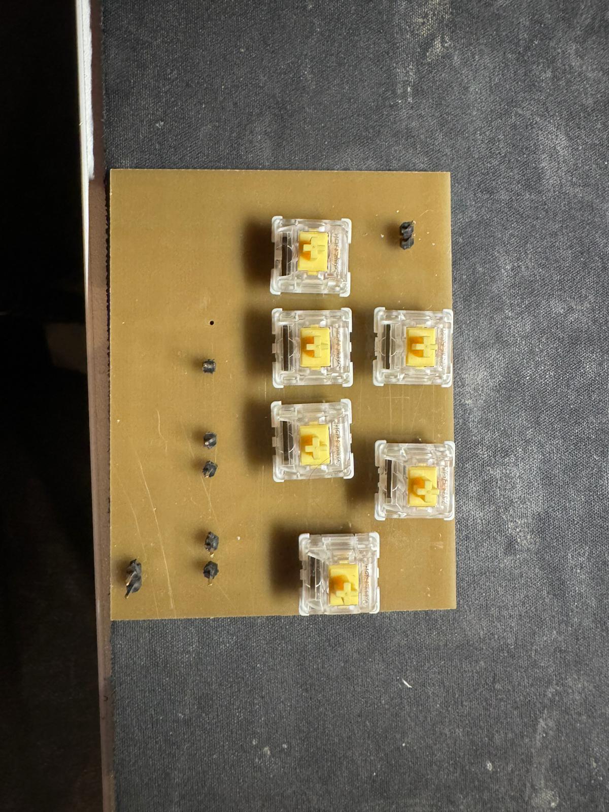
The electrical hardware for this project went through multiple different iterations. Initially I planned on using mechanical keyboard switches for the buttons, but with time this proved both, more difficult and less user friendly. In the end I settled on using a simple 2-Axis joystick for input.
The microcontroller used for this project was the ATtiny1614. More information about the production of the microcontroller can be found here.
Besides the method of input, it was also necessary to provide some sort of output to the user. For this I chose to use a small 1,3-inch OLED screen. The screen was chosen because it is small and relatively easy to use. The screen was connected to the microcontroller using the I2C protocol.
As another form of feedback for the user I also chose to add a speaker into the project. Normally, adding a speaker to an electrical project can prove to be more difficult than expected. In most cases you would need some sort of amplifier to drive the speaker. Controlling the speaker itself can also require a non-trivial amount of code and computing power. Especially on a limited platform like the ATtiny1614 this could prove difficult. To solve this problem, I chose to use a DFPlayer Mini. The DFPlayer Mini is a small MP3 player module that can be controlled using a simple serial connection between it, and the microcontroller. The module can be used to play MP3 files from a microSD card. The module also has a built-in amplifier and can drive a small speaker directly. This made it very easy to add sound to the project.
Other components used in the project included a small lithium polymer battery, a USB-C charging board, a power switch and a reset button. A full list of components (or very close analogues in cases were the original is no longer available) can be found in the bill of materials.
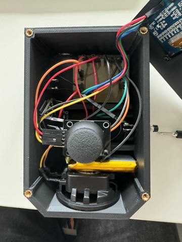
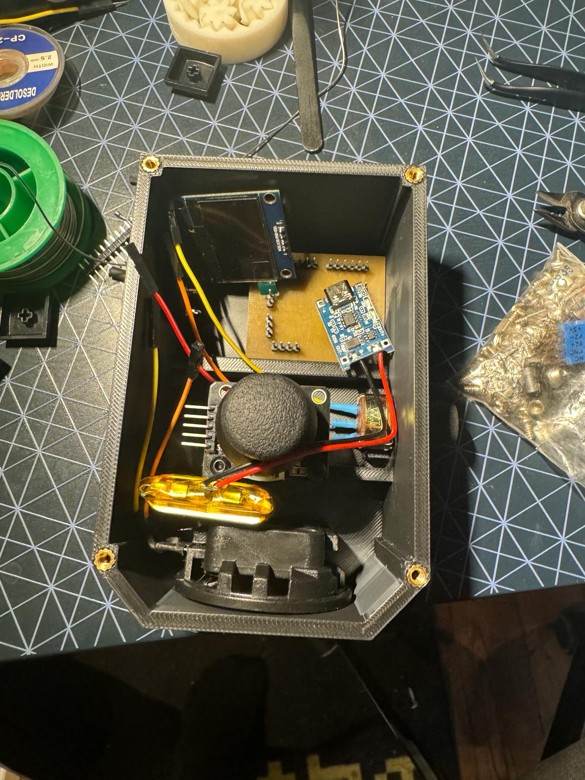
The final electrical assembly can be seen below:
Programming
The programming of the Snakeboy was done using the Arduino IDE. As such the code for the project is written in C++. The code for the project can be found here.
For the different components of the project the following libraries were used:
- DFRobotDFPlayerMini for the DFPlayer Mini
- U8g2lib for the OLED screen
The code consists of multiple different parts.
The first part of the code is the setup function and all the fixed variable definitions. The setup function is responsible for initializing the different components of the project. This includes initializing the screen, the joystick pins and the DFPlayer Mini. The screen specifically is initialized to use the using the I2C protocol for a generic SH1106-Controller running a 128x64 pixel display.
The main part of the code is the game loop. The game loop is responsible for updating the player position (using the move function, checking for collisions (using the checkGameOver), checking if the food was collected (in the checkFood function), and updating the screen (using the drawPixel and draw functions. The game loop also checks for user input and updates the player direction accordingly.
The game loop is also responsible for playing sound effects. The sound effects are played using the DFPlayer Mini. The sound effects are played when the player collects food.
Overall, the coding of the project was relatively straight forward. The most difficult part was the display initialization. It was also somewhat tricky to fit all of the game’s logic into the limited amount of memory available on the ATtiny1614. This occurred for both, the available RAM (which leads to limits placed on the used data structure) and the available program memory.
Discarded Ideas & Problems
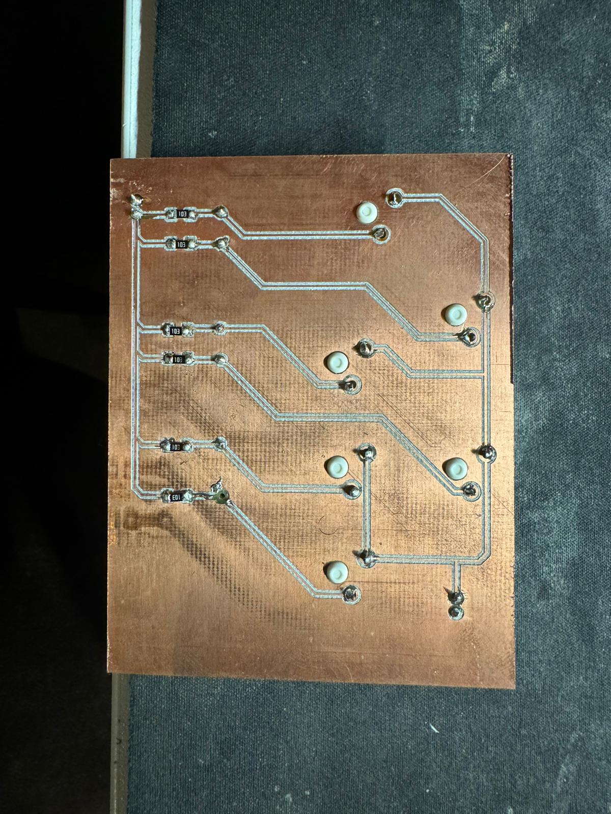
The project went through multiple different iterations. The first iteration of the project was to use a mechanical keyboard for input. This was discarded as it was both, more difficult to implement and less user friendly. For this idea I also produced a small breakout PCB. The finished PCB can be seen below:
The second iteration of the project was to use a small 8x8 LED matrix for the display. This was discarded as it just didnt feel right for snake.
Another case of iteration for this process was the case design. The initial for the case was significantly wider. One of the more refined versions of the initial case design can be seen below:
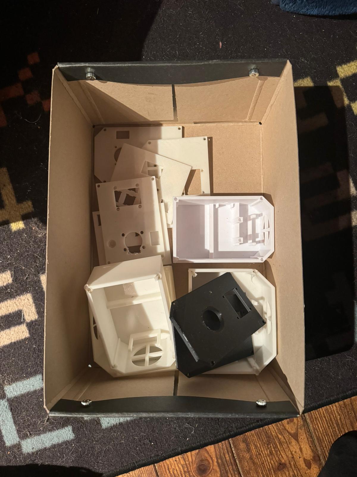
This idea was scraped as it was unnecessarily large and would have been more time consuming to print without giving any real benefits. It would later turn out however, that the final case design was somewhat cramped to fit all of the required wires into it. Throughout the entire case design process, it was also necessary to make multiple different prototypes to test the fit of the different components. This was especially necessary for the joystick and the screen. All in all i ended up printing 5 different versions of the case and about 8 different versions of the top-plate.
The initial design of the snakeboy also had a potentiometer instead of a reset button. This potentiometer was supposed to be used to control the volume of the speaker. This was discarded as the joystick already took up the available analogue-capable pins on the microcontroller. The reset button was then added to the design to replace the potentiometer. Due do this the case design still contains the small mounting slots that would have been used to keep the potentiometer in place.
The wiring was the most difficult part of the project. As the project mostly used Pin-Headers almost all of the wires were jumper wires. As these wires can be somewhat stiff this made the wiring more difficult to manage and with all components installed the case got somewhat cramped.
This picture gives an idea for how space the components alone took up in the case:
Final Assembly & Demo
The final assembly of the project was relatively straight forward. The case was printed and the inserts were installed. After that, the components were installed into case piece by piece.
The first component to be installed was the controller board. It was secured using two mainboard standoffs that got heat-pressed into the case. After that the mainboard could be screwed into those standoffs. The battery was then installed into the specifically designed comportment.
The battery was then connected to the USB-C charging board. This board was placed into the USB-C cutout in the case. The ground pin of the charging board was then connected to the ground pin of the controller board through the power switch. The positive pin of the charging board was then connected to the positive pin of the controller board.
After this the reset switch was inserted into the cutout hole on the right side of the case. This was then wired into vcc on one side, and the GPIO-Pin that was used as the reset pin on the controller board and ground through a pull-down resistor.
After this the speaker was installed into the case in its designed slot at the bottom. The speaker was then connected to the DFPlayer Mini. The DFPlayer Mini was then installed into the case and connected to the controller board using jumper wires.
The next component was the OLED screen. The screen was installed into the top plate of the case using M3-Screws and nuts. The screen was then connected to the controller board using jumper wires.
The last component to be installed was the joystick. The joystick was installed onto the Joystick-Mounts of the case using M3-Screws. The joystick was then connected to the controller board using jumper wires.
The final assembly of the project can be seen below:
Conclusion
The final product was a small, portable, and fun to use game console. A video of the final product can be found here.
The project was also a good learning experience. It was a good way to learn about the limitations of the ATtiny1614 and how to work around them. It was also a good way to further my skills of CAD-Design and 3D printing.
After testing it also turned out that the battery life of the project was quite good. The project could be used for multiple hours without needing to be recharged. The sound quality of the speaker was also quite good. The sound effects were loud and clear. The screen was initially somewhat difficult to read, but after adjusting the scaling so that the displayed pixels were 3x3 pixels in size, the screen was quite readable.
All in all the project was a success and it was a fun way to end the course.
Bill of Materials
- The case was printed using Creality Hyper PLA.
- The display is a 1.3” OLED Display using the SSH1006 Driver
- The 8W Speaker was driven by a DF-Player
- The LiPo Battery was connected using a USB-C Charging board
- The board also used a JoyStick and a Button.
- The board was a custom PCB that was designed and made using CNC. It used an assortment of resistors, pinheaders, capacitors and the AtTiny1614 microcontroller.
Files
All of the files for the project can be found in the Github Repository. The different discarded case versions can be found in the Case-Folder. The used PCB-Designs can be found in the PCBs-Folder. The code for the project can be found in the Code-Folder.